Thin Piece Collet
As described previously, the piece I have now is a 27mm OD, 3mm think brass disk with a ⅛ inch hole drilled in the center. After parting, the parted face is not as nice as the turned face, as well as having paper thin circle of brass protruding around the center hole where the parting tool cut through. I will probably clean this up using a hand file, but if I were game, I would make a Thin Piece Collet for it and use that.
A thin piece collet is a very simple workholder for holding thin, circular pieces, such as washers. It is made from round bar slightly larger in diameter than the desired work piece, turned down in two steps, drilled through the middle, and then split almost in half with a hacksaw or band saw. For example, to hold my 27mm OD, 3mm think brass disk, I would make it something like 60mm long, in three 20mm steps, 10mm OD, 20mm OD, 30mm OD, and drill through the middle with a 6mm drill, then turn a 27mm, 2mm deep insert in the large end, and hacksaw from the large end to 5mm short of the small end. I would draw up the piece in QCad, but it has been a while and I have forgotten how to use it, so I will do some povray 3D renders instead.
 Rotating Thin Piece Collet |
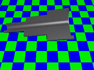 Cross Section of Thin Piece Collet |
The work piece is inseted into the end of the collet, and then the collet is placed with the back of the first step against the chuck jaws, and the jaws grip the middle step, clamping on the work piece.
The collet can be reused by inserting a 6mm place holder into the drilled hole, clamping it without any workpiece, optionally facing it off and creating a new insert in the end. This is described in Lathework: A Complete Course by Harold Hall which I am reading at the moment.
Posted 2006-09-01. Permalink. Send Comment.
Parting off
Unfortunately, I did not take any pictures, but hopefully I will remember to take a picture of the part when I am next at the lathe.
First, I center drilled the crank (a ⅛ drill). This may have been a mistake, as the ⅛ shaft is somewhat of a looser fit that I would like, but since it is meant to be silver soldered in, it probably will be ok as long as I can keep it square while soldering.
Then I parted it off. The parting went very well, I'm not sure if that was because it was brass (probably good machining brass), because I've slowed the lathe down, or (and I think this may be it) because I recently learned that when setting up the parting tool you should use the dial gauge to get it perfectly square. This is obvious in hindsight, but many things are obvious in hindsight!
The parted face is almost as smooth as the faced face (not quite, but almost), although a thin circle of brass protrudes from the center drilled hole (my parting tip should have been angled slightly to avoid this, but since I do not have a grinder and have never learned how to make my own tools, I use what I have. Still, with a bit of filing (or perhaps using a drill bit by hand to very mildly countersink the hole), as well as a bit of filing around the circumference of the parted side will have it nicely finished off.
Remaining for the crank is to drill and tap the outer hole and to mill away large parts of the crank. Since I have never tapped a hole, and my milling experiences have had rather poor results to date, this may prove interesting!
Posted 2006-08-27. Permalink. Send Comment.
Starting on Crank
Hurray, I made a start! I spent quite a while ditzing around, driving back to get the shed key I forgot, swapping the three jaw chuck back in, dropping the speed to 400 rpm, but finally chucked the brass part and faced and turned it to 27mm. Next I need to center drill it and then part it off (always exciting).

Not a huge amount of progress, but a start nonetheless!
One trick I have learned is to use a block of wood between the carriage and the tailstock, with the tailstock locked down to avoid the carriage moving while I am facing or turning (since no one is holding the handwheel).
Posted 2006-08-12. Permalink. Send Comment.
Book Review: Workshop Drawing by Tubal Cain
I want to learn to better read and write plans, and Workshop Drawing by Tubal Cain has the perfect content to suit my needs. It is well targetted and has an appropriate level of detail with lots of examples and is easy to read. It shows a bit of its age with discussions on how to sharpen pencils with knife and file where most of us would be using a computer CAD package (I use QCad). But even so, it is possible for a novice to lear quite a lot from this book.
So I would love to love it, but unfortunately, the editing really lets it down. I was worried when I found a typo in the first paragraph of the introduction, but the thing that really hurts the book is the new edition has “completely new illustrations and technical drawings” and unfortunately many of the illustrations no longer match the text (for example, the text will refer specification to arrows in a particular drawing, but there are no arrows in that drawing, leaving the poor novice wondering what is meant).
Posted 2006-08-10. Permalink. Send Comment.
Parts
I unwrapped the various parts (all neatly wrapped in newspaper for delivery) and took the following picture:

Hmm, it is going to take some doing to turn all those lumps of metal into an engine!
Posted 2006-07-30. Permalink. Send Comment.
A Bit Overwhelming
I got a chance to glane through the kit. The kit consists of:
- A woodend base display board
- A bunch of metal disks and rods
- An acrylic disk
- A plastic connecting tube
- Somes screws
- A whick
- A list of components and the parts (or parts of parts) they use.
- A bunch of A3 sheets with construction diagrams.
- An Engine Troubleshooting page.
- An Engine Maintenance page.
I was hoping for more of a step-by-step construction plan, but the plan does appear to have everything needed. The first components requires silver and soft soldering, which I’ve never done before so that will certainly be a new experience (and probably require some new tools).
While I was already expecting the project to take many years of very part time work (with two young kids, very part time is as much as there is!), but it is all a bit overwhelming. Still, having built a solar powered car, I am sure I'll manage it eventually!
Posted 2006-07-29. Permalink. Send Comment.
The Kit Arrived
The kit arrived very quickly, including a wooden base display board.
Posted 2006-07-28. Permalink. Send Comment.
The Start
I have wanted to build a small engine for a long time. Having dealt with the mess of petrol engines from my model plan flying days, I’d rather something a bit cleaner. After discovering the Stirling Engine, I figured that would be the way to go.
A Stirling Engine is really quite amazing, it has a sealed volume of air that is alternately heated and cooled, and thus expands and contracts. This pushes and pulls a piston which does the work. The air inside is heated and cooled by moving it between hot and cold areas using a displacer which alternately occupies the part of the sealed volume that is hot (thus allowing the air to cool) or cold (thus allowing the air to heat).
Stirling Engines are very simple, having no valves and only a few moving parts, namely the power piston, the displacer, the flywheel and crankshaft, and connecting rods.
So I started looking around for a possible engine to build. I found a great site by Jerry E. Howell with some great plans, but being in the USA and not accepting credit cards made it a bit more challenging. Then I found the plans for A low temperature Stirling Engine by Penn Clower which looked good, but then got stymeed trying to find the materials (it seems that half the time for any project I do is just spent finding where to buy the materials!).
Then I found the MiniTech site and their kits, so I purchased the “Hot Air Engine Vertical see thru” (HAE-VH) kit. And so it began.
Posted 2006-07-26. Permalink. Send Comment.